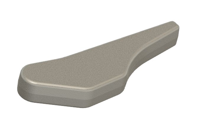
Designing for Forging

Short article on forging manufacturing process and factors to be considered when designing for forging
Die Forging is a bulk forming manufacturing process very commonly used for high strength and durability applications as an alternative to casted and machined parts.
The high forces required to form the shape make the material stronger as the microstructure gets re-arranged and internal voids which maybe present are removed.

Parts of a Forging Die

The excess material goes into the gutter cavity through the Land in the die and is called flash .
Forging parts are generally characterized by the parting line which separates the upper and lower die. Location of the parting line is detrimental to the outcome of the part in its geometry as well as strength.
Draft allowances : For easy removal of the part from the die after forging is done

Forging vs Machining :
The arrangement of grains (continuous lines) is a big factor in strength and durability.
For the same geometry , forging is always stronger than the machined part.
An example of symmetrical parting line for a symmetrical grain structure in the forging


Parting line location should be at the cross section of maximum area.

Out of the three options, Option C is superior.
Design features: Ribs , webs
Very often Design features like Ribs and Webs are added to the forging to reduce the weight .

Case study in Design for forging:
Transformation of solid part to forgeable part geometry.

Considering the Solid part as input :

Step 1 : Adding fillets and draft considering a central parting plane


Step 2 : Adding Rib , depression to the design.

Step 3 : Adding emboss with draft sides and fillet radii

Another example of Design for forging:

Categories: : DFM
 Mufaddal Rasheed