GD&T Projected tolerance zone
 Mufaddal Rasheed
What is the concept of projected tolerance zone in GD&T ? How to interpret it on the drawing?
The projected tolerance zone (PTZ) is a special modifier used in GD&T to control the orientation and location of features—typically holes—based on how they are used in assembly. It accounts for how features like pins or fasteners extend out of a part and interact with mating parts
Consider this example of a plate being assembled on a block with a threaded hole
Part A is the block with a threaded hole M10
Part B is the plate with a clearance hole

Part A Drawing

Tolerance zone for the M10 threaded hole:

The problem of misalignment:

There has to be a relation between tolerance zone of threaded part and the part with clearance hole
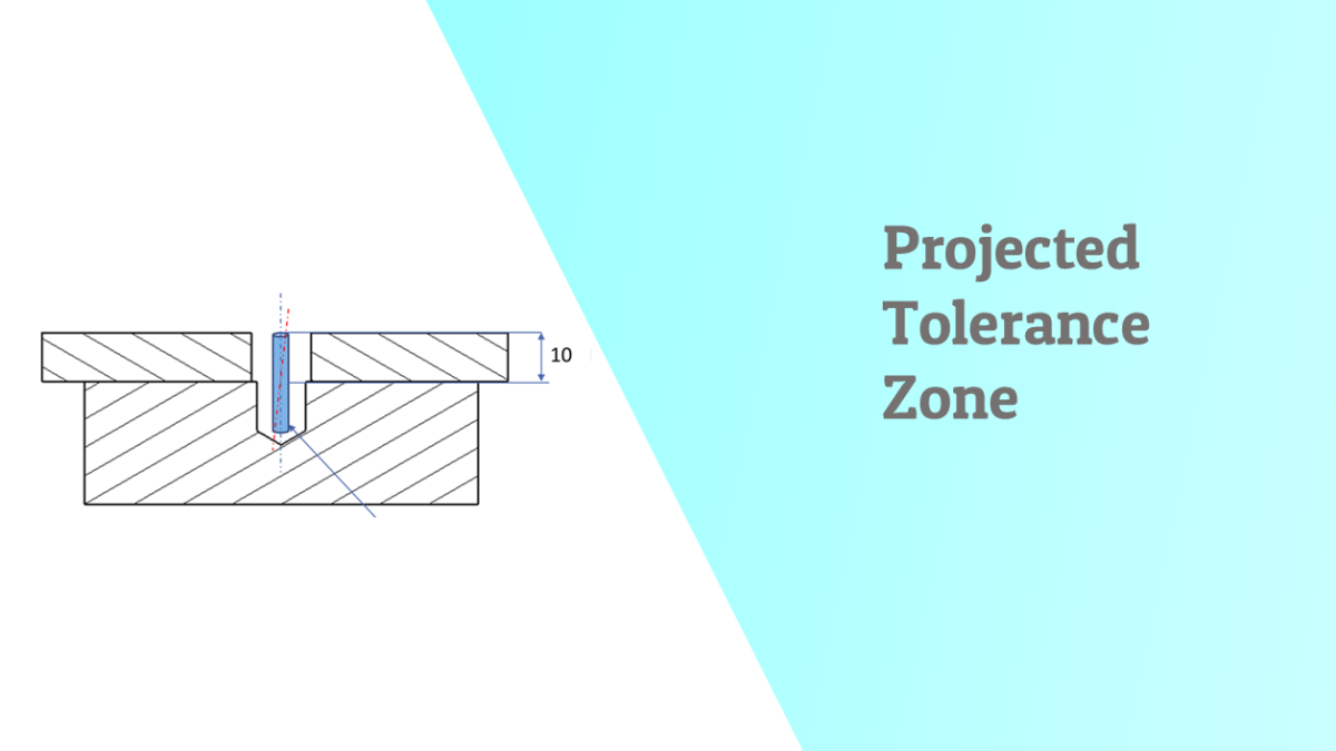
Modified drawing of the block with threaded hole.

The change: in the feature control frame a P symbol and a number is added indicated projected tolerance zone and the length of projection.
What it means :

Now this projected tolerance says that Part B – the mating part also has to be located such that it satisfies the projected tolerance zone
Why projected tolerance zone is important
Without the projected zone:
- The hole may pass inspection but cause misalignment in the assembled product.
- Functional failures may occur when the mating part doesn't fit due to angular variation of the pin or bolt.
It helps ensure fit, alignment, and stress-free assemblies
Another example of application of projected tolerance zone :


Categories: : GD & Tolerancing