GD&T scheme interpretation
 Mufaddal Rasheed
A short article on Interpretation of GD&T schemes on drawings with multiple examples
A key skill in GD&T is correctly identifying and deciphering GD&T annotations on the drawing.
What they mean and what they imply .
Key Aspects of Interpreting a GD&T Drawing
- Feature Control Frame:
This is the backbone of GD&T. It contains the geometric characteristic symbol (e.g., flatness, parallelism), tolerance value, and datum references. Understanding how to read this box is crucial. - Symbols and Characteristics:
Familiarity with GD&T symbols like straightness (─), flatness (⏥), circularity (○), position (⌀), etc., is essential. Each symbol defines a specific type of allowable variation. - Datums and Datum Reference Frames (DRF):
Datums are theoretical planes, axes, or points from which measurements are made. Understanding the datum hierarchy (primary, secondary, tertiary) helps interpret the orientation and position tolerances correctly. - Tolerance Zone:
The type and shape of the tolerance zone (cylindrical, planar, etc.) vary with the geometric control applied. Interpretation involves knowing how the part can deviate while still remaining within this zone. - Material Condition Modifiers:
Symbols like MMC (Maximum Material Condition), LMC (Least Material Condition), and RFS (Regardless of Feature Size) affect how tolerances are applied and inspected. - Basic Dimensions:
These are theoretically exact values (shown in a box) and are used to locate features. They are always associated with geometric controls and require a tolerance in the feature control frame.
Here are a series of drawings with their interpretations with respect to Geometrical Dimensioning and Tolerancing.
Drawing 1 :

Interpretation:
Straightness of the axis of the pin should lie within a cylindrical tolerance zone of 0.5 mm at the MMC (maximum material condition) of the pin i.e. at 50.5 mm .
If the size of the pin manufactured away from MMC then bonus tolerance applies.
- Virtual condition of the pin is 49.5-0.5 = 49 mm
- Rule #1 is being overridden
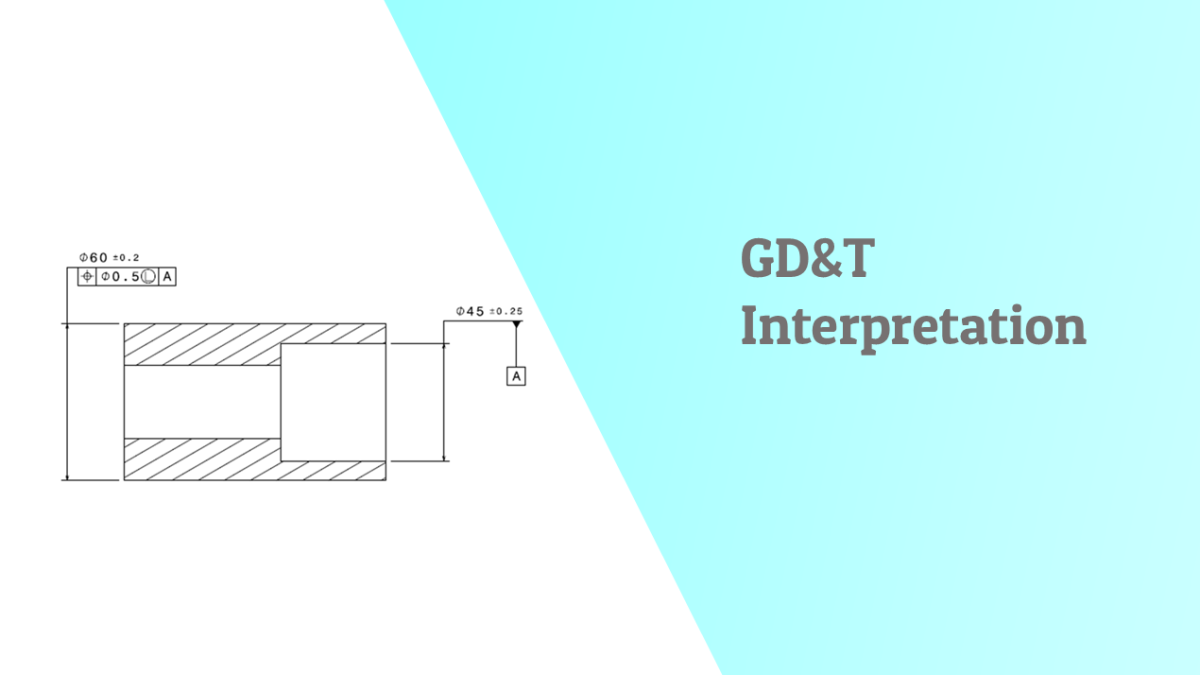
Drawing 2 :


Interpretation :
The outside diameter of the bush with nominal of 60 diameter and size tolerance of +/- 0.2 should be controlled with respect to its position (concentricity) with respect to the Datum feature of size A (the hole) at its Least material condition ( 59.8) within a tolerance zone of 0.5
If the size of manufactured bush outside diameter is away from LMC then there will be bonus tolerance.
The hole with nominal size of 45 diameter and size tolerance of +/- 0.25 is primary datum feature A
Drawing 3 :

FCF 1 :
Position of the hole of nominal size 10 with a size tolerance of +/- 0.1 should be within a cylindrical tolerance of 1 mm diameter with respect to datum A, B and C .perpendicular to Datum A, Located from Datum B with basic dimension of 48 and from datum C with basic dimension of 48-21 = 27 mm
The position control is regardless of feature size
FCF 2 :
Position of the hole of nominal size 25 with size tolerance of +/- 0.15 should be within a cylindrical tolerance zone of 0.5 mm diameter with respect to Datum A and Datum B located from datum B with a basic dimension of 21 and perpendicular to datum A
The position control is regardless of feature size
The feature of size with nominal 25 and size tolerance of +/- 0.15 is also datum feature C.
Categories: : GD & Tolerancing