GD&T angularity
 Mufaddal Rasheed
What is the interpretation of angularity orientation control in GD&T and how is the tolerance zone defined. a short explanation.
Angularity in Geometric dimensioning and Tolerancing is applied to any flat surface which is required to be controlled in its orientation with respect to another reference surface feature on the part .
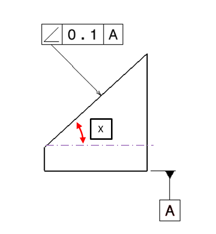
Here is a callout of angularity on an inclined face of this part.

The bottom surface is the primary datum feature and with respect to the bottom surface the angularity of the inclined surface has to be within a tolerance zone of 0.02.
The interpretation of this callout is that as manufactured surface and points of the surface should be enclosed within a tolerance zone of 0.02 which is at the basic angle 35 .

The tolerance zone is not fixed in its location with respect to the datum reference (A) rather it is fixed in its orientation.
Wherever the as manufactured surface may be, it should be within a tolerance zone as defined with respect to its orientation.
Angularity is used when the surfaces are not perpendicular or parallel to the reference and can be controlled with respect to more than one datum.
Here is another example and how it is generally inspected:
Inspection of angularity is done by making the inclined surface parallel to the gauge horizontal .
The angle of rotation is nothing but the basic angle dimension “x”
Then a dial gauge is moved across the surface targeted
If total deflection on dial gauge is beyond the value mentioned in callout then the part is considered not acceptable as per angularity control applied.

Example of angularity applied to sheet metal parts surfaces.

Learn more about how to Interpret GD&T callouts from this Free e-book on GD&T interpretations
To learn more about GD&T have a look at this course
Geometric Dimensioning and Tolerancing: Basics
Explore more topics in GD&T :
What is virtual condition in GD&T
Factors in Specifying tolerance
GD&T Regardless of feature size
GD&T maximum material condition
What is datum feature modifier
What is actual mating envelope
What is 3-2-1 principle in tolerancing
Applying GD&T scheme to a bracket
GD&T applied to patterns of features
Tolerance stack up analysis of a simple part
What are material conditions in GD&T
Composite position tolerance in GD&T
What are datum targets in GD&T
Verification of manufactured GD&T drawing
What are simultaneous requirements in GD&T
Calculating the geometric tolerance of a part
Developing GD&T scheme for a part
Traditional tolerancing vs GD&T
Categories: : GD & Tolerancing