How to learn GD&T the efficient way for design engineers
 Mufaddal Rasheed
A Systematic approach to learning GD&T from basics to advanced to apply concepts in design engineering and product development
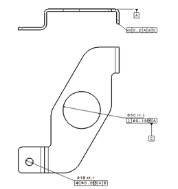
Engineering drawing or manufacturing drawing is the document which is created by the design engineer and passed on to the manufacturing and inspection teams in a manufacturing setup.
The drawing conveys design intent and a large part of it is about defining the tolerancing schemes of various design features.
GD&T is the systematic way of tolerancing components which makes the communication clear regarding quality and meeting design intent. Removing ambiguity and confusion between design and manufacturing .
Learning about GD&T is valuable and highly sought after skill for design engineer.
So, how to systematically Learn GD&T?
There are generally three levels
- Basics
- Interpretation
- Application
Basics includes the understanding of engineering drawings, views, tolerances and vocabulary, terms which is associated with technical drawings. Meanings of symbols and rules.
Interpretation is next level which includes interpreting existing drawings and making sense of the geometric controls which have been applied on them, what are the meaning of them as a whole. How to visualize the tolerance zones of the various geometric control?
Application level is when you can pick and choose which type of control scheme to apply based on the application. Naturally, applying GD&T confidently requires understanding of Basics and Interpretation.

What to learn at the Basics level ?
- How is tolerance decided for an application ?
- What are features, features of size and material conditions?
- Why GD&T is needed over traditional tolerancing method?
- Comparison of Co-ordinate tolerancing with GD&T.
- What is Rule #1 and what is MMC , LMC
- What are datum and how are they defined?
- How is a Datum reference frame created? Their variants for different types of features
- Understand tolerance zones
- Understand the 14 symbols and what they mean ?
- How is Form, orientation, position , runout and profile inspected?
- What is Bonus tolerance and what is virtual condition
- Condition for successful assembly
What to learn at the Interpretation level ?
- If a GD&T drawing is given , how to make sense of the various feature control frames?
- How to understand the Datum scheme applied?
- How to visualize the tolerance zones with relation to datum?
- How to calculate the amount of tolerance available for certain condition of part?
What to learn at the application level ?
- Defining a GD&T scheme based on the important functional features of the component
- Creating an optimized GD&T scheme
How to improve GD&T skills and knowledge. Some quick nuggets
1. First stop looking at GD&T as just a set of symbols or annotations and understand the concepts of size, form, orientation, and position of features.
2. The difference between features and features of size
3. Understand the differences in tolerance zones.
4. Concept of datum. Differentiating Datum feature, simulated datum feature and theoretical datum.
5. The spatial reasoning of geometric relationships in terms of orientation and position.
6. Concept of composite tolerances in position and profiles.
7. Connection between Design, inspection and manufacturing of a dimension/ tolerance specification.
8. Understanding Design intent underlying the dimensioning and tolerancing scheme.
9. Take components as inputs and Create GD&T schemes. Trouble shoot them and improve .
Learn more about how to Interpret GD&T callouts from this Free e-book on GD&T interpretations
To learn more about GD&T have a look at this course
Geometric Dimensioning and Tolerancing: Basics
Geometric Dimensioning & Tolerancing : Advanced concepts
Explore more topics in GD&T :
What is virtual condition in GD&T
Factors in Specifying tolerance
GD&T Regardless of feature size
GD&T maximum material condition
What is datum feature modifier
What is actual mating envelope
What is 3-2-1 principle in tolerancing
Applying GD&T scheme to a bracket
GD&T applied to patterns of features
Tolerance stack up analysis of a simple part
What are material conditions in GD&T
Composite position tolerance in GD&T
What are datum targets in GD&T
Verification of manufactured GD&T drawing
What are simultaneous requirements in GD&T
Calculating the geometric tolerance of a part
Developing GD&T scheme for a part
Traditional tolerancing vs GD&T
Categories: : GD & Tolerancing